
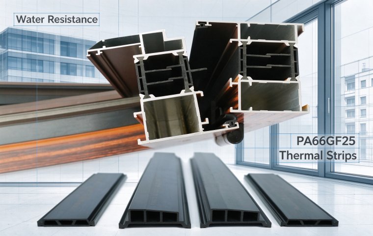
Water Resistance Test Standard, Test Control, Working Condition Selection and Quality Judgment of PA66GF25 Thermal Break Strips
This paper analyzes the water resistance of PA66GF25 thermal break strips based on GB/T 23615.1‑2017. It compares two test methods, sorts typical failure modes, proposes grade selection for different working conditions and process control measures. Standardized contract suggestions are provided to control moisture ageing risks and ensure long‑term structural safety of thermal barrier profiles.
Introduction
Water resistance is a mandatory test item for the acceptance of thermal break strips and thermal barrier profiles. National standard GB/T 23615.1-2017 specifies two parallel water resistance test protocols. Data obtained from different test methods are not directly equivalent, which easily causes disputes during inspection, acceptance and supply contract execution. Meanwhile, the required water resistance grade of thermal break strips varies greatly depending on regional working conditions and building types. Ordinary inland residential buildings, rainy southern regions and coastal high-humidity salt-spray environments impose completely different requirements on hydrolysis-resistant formulations. This paper provides a purely technical analysis focusing on water resistance test standards, key process control points, typical characteristics of non-conforming products, selection logic for different working conditions, and production measures to improve water resistance stability. It contains no product marketing content and is prepared for technical popularization on the Aicaigou platform, helping purchasers, profile manufacturers and inspectors establish unified judgment criteria.
1. Analysis of Water Resistance Test Protocols in GB/T 23615.1
The national standard provides two protocols: ambient immersion test and boiling water test. In the absence of contractual agreement, the ambient immersion test shall be adopted preferentially for arbitration. For the ambient immersion test, specimens are submerged in Grade 3 pure water at 23℃±2℃ for 1000 hours continuously. The boiling water test is an accelerated ageing method, in which specimens are kept in boiling Grade 3 water for 4 hours.
Specimens for assessment fall into two categories: individual thermal break strip specimens and assembled thermal barrier profile specimens. The water resistance assessment of thermal barrier profiles evaluates not only the inherent performance of thermal break strips, but also the synergistic stability of the interlocking interface between thermal break strips and aluminium alloys after water absorption. As clearly specified in the standard, after immersion and cooling to the standard condition, the characteristic value of transverse tensile strength at -20℃ shall be tested. Its reduction range shall not exceed 30% of the corresponding index before immersion, and the low-temperature transverse tensile characteristic value shall also meet the minimum limit requirement. This is the core critical index for engineering acceptance.
Many purchasers misunderstand that the 4-hour boiling water test and the 1000-hour ambient immersion test are interchangeable. A large number of comparative test data show that the two methods follow different failure paths: the boiling water test drives hydrolysis under short-term high temperature to rapidly assess the hydrolysis resistance of the matrix; the 1000-hour ambient immersion test is dominated by slow water absorption and gradual interface debonding, which better simulates real service conditions such as long-term dampness and condensation infiltration on doors and windows. Some specimens pass the boiling water test yet suffer slow interface debonding after prolonged ambient immersion and finally fail the reduction requirement. Therefore, for coastal and high-humidity curtain wall projects, it is recommended to specify the 1000-hour ambient immersion test as the acceptance basis.
Apart from the Chinese national standard, European standard EN 14024 also includes water immersion conditioning for pre-test state adjustment before transverse tensile and creep tests. It shares a similar principle with the domestic standard, simulating mechanical property retention after long-term moisture intrusion into thermal barrier structures. This technical clause is frequently referenced for export profile orders.
## 2. Pre-treatment, Specimen Preparation and Inspection Control for Water Resistance Tests
Water resistance test results show high dispersion. Many abnormal test outcomes stem from non-standard specimen preparation, pre-treatment and conditioning rather than inherent quality defects of thermal break strips. First of all, specimens shall be cut away from extrusion ends, bent sections, scratched surfaces and microcracks, with neat cutting edges to avoid prefabricated stress defects. Specimens with residual internal stress tend to crack prematurely after water immersion due to combined stress release and water absorption swelling, leading to false low test results.
When placing specimens into water, all specimens shall be fully submerged with gaps reserved between specimens and between specimens and the container wall to allow free water exchange without stacking or compression. The water shall be replaced periodically during immersion to prevent microbial growth and impurity precipitation that alter the aquatic environment, and to avoid impurities adhering to specimen surfaces and interfering with moisture penetration paths. After immersion, specimens cannot be tested immediately. They shall be conditioned in accordance with standard requirements: wipe off free surface water and store them in a standard temperature-humidity environment for sufficient time to achieve uniform internal moisture distribution. Immediate testing right after retrieval causes huge differences in moisture content between the surface layer and core layer, resulting in drastic fluctuations of modulus and strength and poor repeatability.
In addition, raw material batches, extrusion processes and storage histories must be unified for comparative tests. Thermal break strips that have absorbed moisture during long warehouse storage have elevated initial moisture content, whose performance attenuation curve after immersion differs completely from that of identical strips produced with freshly dried material. For formal laboratories conducting water resistance comparison, specimens are generally dried to constant weight to unify initial moisture content before immersion, ensuring a consistent comparison baseline.
3. Typical Failure Modes and Root Cause Tracing for Thermal Break Strips Failing Water Resistance Tests
Non-conformity in water resistance tests mainly falls into three failure modes, each corresponding to distinct quality causes.
Type 1: Excessive strength reduction with fracture inside the thermal break strip matrix. This is mainly caused by insufficient hydrolysis resistance of raw materials. Typical cases include ordinary PA66 resin without hydrolysis stabilizers, heavy blending of recycled PA6 material, or even PA6 matrix falsely labelled as PA66GF25. The amide bond of PA6 has poorer stability and a much higher hydrolysis rate than PA66. After long-term immersion, molecular weight drops rapidly, accompanied by sharp deterioration of matrix toughness and strength.
Type 2: Fracture occurs at the interface between glass fibre and resin, with smooth glass fibre and poor resin encapsulation observed on fracture surfaces. The root cause is mismatched glass fibre sizing systems. The surface treatment agent of glass fibre has weak hydrolysis resistance. Water penetrates along the interface channel between glass fibre and matrix and damages interfacial adhesion, triggering debonding. Even if the base resin is qualified, failed interfaces prevent glass fibres from transferring load effectively, leading to rapid deterioration of overall mechanical performance.
Type 3: Individual thermal break strip specimens pass the test, while assembled thermal barrier profiles fail the water immersion test. This problem is mostly related to strip insertion and composite processes, such as shallow interlocking teeth, insufficient rolling crimping and dimensional deviation of profile grooves. After water enters interlocking gaps, the wedging effect of water enlarges interface gaps and reduces interlocking bonding force, resulting in tensile failure of profiles, rather than water resistance defects of thermal break strip raw materials.
There is also a hidden defect: specimens barely meet the water resistance index but suffer continuous performance degradation after wet-dry cycles. Single water immersion may be acceptable, yet repeated drying-absorption cycles accumulate micro interfacial damage and trigger premature failure during service. Such risks are more likely to emerge in rainy southern areas with frequent day-night condensation.
4. Selection Logic of Water Resistance Grades for Thermal Break Strips under Different Building Conditions
For doors and windows of ordinary residential buildings in inland dry regions, environmental humidity fluctuates mildly and condensation rarely accumulates inside cavities. Standard compliant PA66GF25 thermal break strips satisfy water resistance requirements and can be accepted per basic national standard provisions. For rainy areas south of the Yangtze River with prolonged high humidity during the plum rain season, condensation tends to gather inside door and window cavities. Modified PA66GF25 grades added with hydrolysis stabilizers are preferred to slow down hydrolysis under long-term immersion.
Coastal conditions represent a severe service scenario for water resistance. Apart from pure water immersion, water vapour contains chloride ions, and saline environments synergistically accelerate interfacial corrosion and hydrolysis. Ordinary water-resistant formulations cannot meet long-term service requirements. Special hydrolysis-resistant PA66 formulations are required, together with drainage channels designed on profiles to reduce prolonged water pooling around thermal break strips. For ultra-low-energy buildings and passive houses, thermal insulation structures remain sealed for a long time, maintaining high cavity humidity. Both water resistance and creep resistance shall be assessed simultaneously during material selection instead of only checking initial mechanical properties.
Meanwhile, structural optimization at the design stage can ease the requirement ceiling of thermal break strip water resistance: drainage holes set on profile cavities block rainwater from directly entering the thermal break zone and lower the risk of long-term immersion of thermal break strips. This is a more economical and reliable control measure than simply upgrading the hydrolysis resistance grade of materials. Combined material performance and structural protection are required to mitigate water-induced ageing risks.
5. Production Process Control Measures to Improve Water Resistance Stability of Thermal Break Strips
Water resistance is determined not only by raw material formulation but also by extrusion and post-treatment processes, which substantially affect the final water resistance performance of finished products. Raw material drying serves as the first critical control point. PA66 pellets must be fully dried before extrusion. Excessive moisture in raw materials generates tiny bubbles inside the melt during extrusion, forming internal voids that act as fast moisture penetration channels and greatly accelerate water absorption and hydrolysis.
During extrusion cooling and shaping, cooling rate affects crystallinity. PA66 matrix with higher crystallinity has a smaller amorphous fraction, fewer diffusion pathways for water molecules, lower equilibrium moisture content and better water resistance stability. Rapid cooling leads to incomplete crystallization, faster water absorption and accelerated long-term performance attenuation. The temperature profile of shaping dies and cooling tanks directly influences the uniformity of crystalline structure.
Post-extrusion ageing also has an impact. Adequate ageing releases residual extrusion internal stress and suppresses microcracks generated by the superposition of stress and water absorption swelling during wet-dry alternation. If substantial extrusion stress remains inside thermal break strips, stress concentration occurs during water absorption swelling, microcracks expand rapidly, and moisture continuously penetrates along cracks to accelerate ageing and failure.
6. Recommendations on Water Resistance Clauses in Contracts for Procurement and Acceptance
Most disputes between suppliers and purchasers arise from ambiguous descriptions of water resistance clauses in contracts. Several key points shall be clarified in the technical procurement agreement: whether to adopt ambient immersion or boiling water protocol, immersion duration, whether test specimens are individual thermal break strips or finished thermal barrier profiles, limits of transverse tensile characteristic value after immersion, allowable strength reduction ratio, and specimen conditioning conditions. Batch sampling rules can also be specified. For high-humidity and coastal projects, suppliers may be required to provide original water resistance test curves and SEM fracture reports to verify hidden defects such as interfacial debonding.
It should be clarified that qualified PA66GF25 thermal break strips permit reasonable strength reduction caused by water absorption. The 30% reduction margin set by the national standard accommodates the inherent moisture absorption characteristic of polyamide. It is unrealistic to demand unchanged performance after immersion. The core criterion for non-conformity is that performance attenuation exceeds standard limits and structural load-bearing capacity is lost, rather than a mere drop in modulus.
Summary
Evaluation of thermal break strip water resistance must be tied to the corresponding test method, specimen type and service condition. Simple qualitative labels such as “good water resistance” or “poor water resistance” are inadequate. The two water resistance tests specified in GB/T 23615.1 correspond to accelerated hydrolysis assessment and long-term infiltration simulation respectively. Failure locations help quickly distinguish problems originating from raw material formulation, fibre-matrix interface or profile composite processes. Purchasers, profile fabricators and curtain wall designers shall select matching hydrolysis resistance grades according to local humidity, rainfall and salt-spray conditions of the project. Combined with drainage structure design on profiles, ageing risks induced by moisture can be controlled within design allowances to guarantee structural safety of thermal barrier profiles throughout their service life.